D077 Instrument Panel Punching Equipment 3D Exported


Dashboard Punching Machine Catalogue
I. Overview 1
Main technical parameters
12.1 General parameters
12.2 Working environment 1
III. Equipment composition
13.1 Mechanical part
13.2 Pneumatic system
23.3 Electrical system 3
IV. Operation and use 3
4. 1 operation preparation ……………………………………………………………………………………………………………… .3 4
. 2 Electrical operation ……………………………………………………………………………………………………………… .3 4.
3 Manual mode ………………………………………………………………………………………………………………. .4 4.
4 Automatic mode ………………………………………………………………………………………………………………. .5 4.
5 Parameter settings ………………………………………………………………………………………………………………. .6
V. Operation process 6
VI. Maintenance and repair
66.1 mechanical parts of the maintenance and repair
76.2 pneumatic system maintenance and repair
76.3 control system maintenance and repair 7
Seven, installation instructions 7
VIII. Accessories / wearing parts / spare parts 7
IX. Provide information 8
X. Appendix (electrical schematic) ……………………………………………………………………………………………………. .8
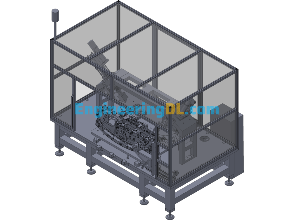
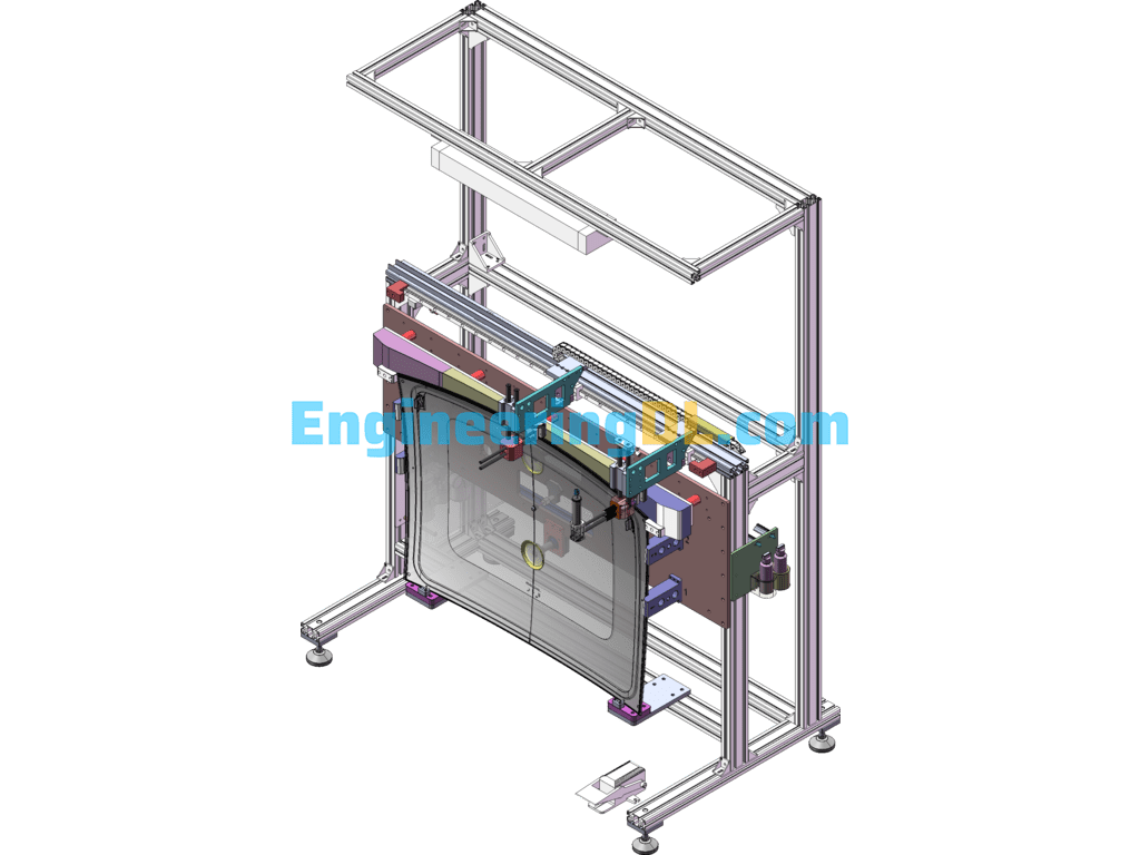
I. Overview
This equipment is used in the production workshop, mainly for punching the vent holes on both sides of D077 products and drilling the frontal ??7 wire harness holes. In addition to D077 products, this equipment is not applicable to other products, punching work is automatic, drilling work is semi-automatic.
II. Main technical parameters
2.1 General parameters
Equipment model: ZKBC-WL-001
Maximum dimension: 2900mm??1650mm??2200mm (length??width??height)
Total weight: about 4.5 t
Motor power: 2.5 kW
Maximum output force of pneumatic-hydraulic cylinder: 10t
Heating temperature: less than 60???
Production tempo: 110 seconds / piece
Noise:
???60db2.2 Working environment
Supply voltage: AC220V??10%; 50Hz??2%
Relative humidity: ???95%RH
Working temperature: 0???40???
Compressed air pressure: 0.6MPa
Third, the equipment composition
The main components of the equipment can be divided into, mechanical parts, pneumatic system and electrical system.
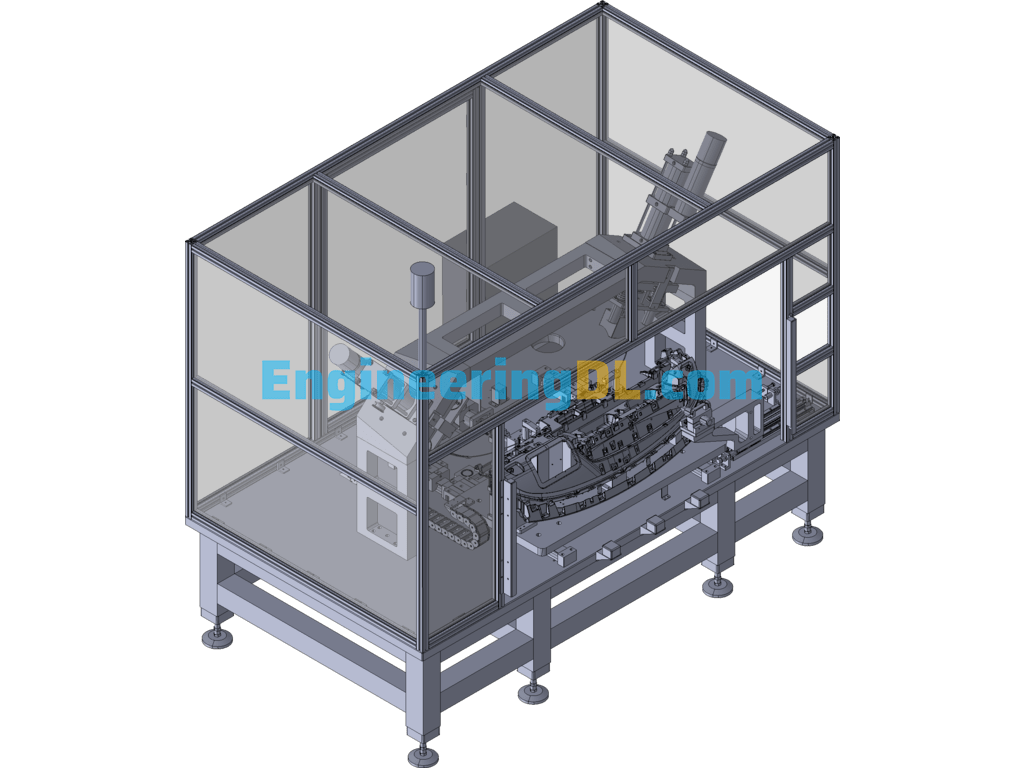
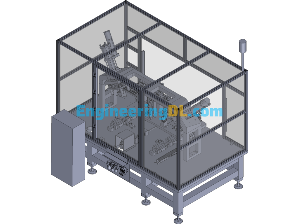
3.1 Mechanical parts
The equipment mainly consists of base, servo motion system, positioning mechanism, stamping system, temperature control system and drilling mechanism, etc.
3.1.1 Base
The base is made of 120×120 square steel pipe welded with 50mm thickness iron plate, which can withstand large external force and ensure that the equipment will not be deformed in the process of stamping and use. The base is supported by adjustable feet with an adjustable height of 100mm up and down.
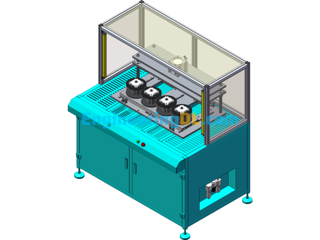
3.1.2 Self-service motion system
The self-service motion system is mainly composed of servo motor, ball screw, tire tool and clamping cylinder. Servo motor and ball screw using coupling connection, the accuracy of the moving part can reach 0.015mm. tire tool is installed with sensors to detect the presence of the product, the equipment can not start when the product is not installed, put the product to ensure the accurate positioning of each positioning point, the product into place, to avoid interference with other parts of the movement.
3.1.3 Positioning mechanism
The positioning mechanism includes two ejector cylinders and positioning sleeve and pins installed on the base of the equipment, the positioning mechanism plays the role of secondary positioning of the tire tool and bearing the lateral shear stress of the system, and can play a role in improving the positioning accuracy of the tire tool and protecting the linear guide and ball screw.
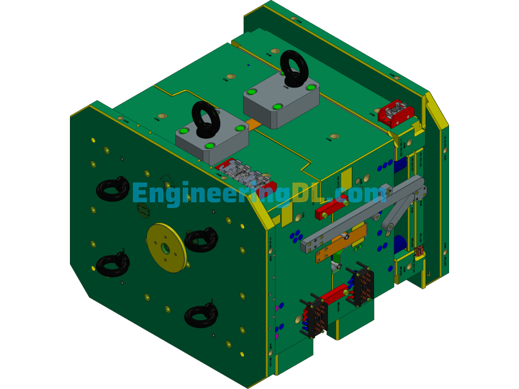
3.1.4 Stamping system The stamping system is the main part to complete the stamping of the equipment, which includes two separate parts, left and right, two parts using The gantry beam is fixed to the base of the machine, and each part includes the pneumatic-hydraulic booster cylinder, floating joint assembly, guide pillar, guide sleeve and punch.
3.1.5 Temperature control system
The temperature control system consists of a heating plate, a heating rod and a temperature sensor. The heating system is used to heat the punch to reduce the cutting edge burr by changing from cold cutting to hot cutting. The heating temperature of the heating system is less than 60???, and the resolution of the temperature sensor is 0.1???.
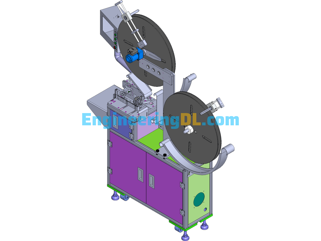
3.1.6 Drilling mechanism
The drilling mechanism is designed as semi-automatic, which includes rodless cylinder, linear guide, pneumatic drill, linear bearing and buffer, and other parts. The left and right movement of the mechanism is automatic, and the drilling action is manual work.
3.2 Pneumatic system
The pneumatic system mainly plays the role of control and positioning.
The air source processing part includes filtration, oil and water separation and pressure adjustment function. The control part is mainly electromagnetic reversing valve, which is centrally controlled by programmable logic controller (PLC), and the user can realize the action control of the actuating element by operating the button. The actuating element is a cylinder, and the movement of the cylinder is used to realize the functions of positioning and stamping, etc.
3.3 Electrical system
The system consists of servo motor, servo controller, PLC, etc., which is controlled by PLC.
Operation and Use
4. 1. 1. Operation preparation:
1) Check whether all kinds of parts in the system are in the correct position before use.
2) Check whether the oil level of the gas-hydraulic cylinder is in the range indicated by the level meter.
3) Check whether there is any loosening of the pipeline interface and fastening screws.
4) Check whether the rear side access door is closed.
5) Check whether each moving part is in the original position.
6) Check whether there is no one and miscellaneous objects at the work station. No one should be under the equipment.
If everything above is normal, you can put it into operation. In the process of using the equipment, no debris can be stacked in the work station, and no one can be under the equipment. If any abnormality is found during operation, the machine should be stopped for inspection and put into operation after troubleshooting.
4.2 Electrical operation
1. The operator should check all parts of the machine before commissioning to ensure that the machine is properly commissioned.
2. Grounding: The machine should be grounded to protect the machine, and the grounding resistance should be less than 0.5 ohm.
3. Close the air switch on the electrical box.
4. Close the circuit breaker inside the power distribution box and send power to the equipment.
5. Turn the key switch on the panel to power on the equipment and press the power button on the panel to power on the machine.
6. Wait for the equipment to power on, normally it takes 30 seconds to power on.
7.
Auto jump to manual or automatic screen after the power-on screen is finished.
Notes.
The screen displayed after power-on completion is determined by the state of the manual-automatic transfer switch.
When the reset indicator on the panel is on for a long time, check whether the system status window indicates an error message.
4.3 Manual mode
1. Select manual from the “Manual/Auto” selection switch, and the screen will jump to the manual screen. The manual screen selects the corresponding execution status, and then presses “manual forward” and “manual backward” to operate.
2. In manual mode, you can set parameters and check each status.
3. (1) In the manual mode, click “Tighten and loosen compression cylinder”, press the manual forward button to make the compression cylinder in the compression state, click “Servo motor in and out”, press the manual forward or backward to run the motor to the punching position, click “Jacking cylinder lift”. “Press the manual forward and manual back button, observe whether the jacking cylinder lifts freely, if there is deviation, adjust the front and rear position of the motor.
Manual interface (2) In manual mode, click “servo adjustment”, enter the servo adjustment screen, ensure the pressing cylinder pressing state, booster cylinder lifting state, jacking cylinder lowering state, click “data initialization”, “positioning start”. “Positioning start”
When the equipment stops at the home position, write down the number of pulses, then divide the number of pulses by 2900, and input the result into the “displacement setting” value input. (The factory setting is about 520mm)
Positioning adjustment
4.4 Automatic mode
1. Select “manual/automatic” selector switch as automatic, and the screen will jump to automatic screen.
2. Place the workpiece, press the two-hand start button, slide the sliding cylinder into place, hold the start rotation handle manually, and punch.
3. The automatic operation starts, the whole automatic operation is protected by the grating, do not block the grating. If blocking, press the reset button for 1 second and then release it.
4.5 Parameter setting
1. parameters have been set at the factory, can not be changed at will.
2. temperature alarm value set to be greater than the upper limit of the temperature setting.
3. password is 888888.
V. Operation process.
Start the work Start the power supply of control cabinet and touch screen Put in the workpiece Press the two-hand start button Drilling mechanism in place Drilling manually After finishing, press the two-hand start button again Clamping cylinder clamping The tire tool moves to the working position Positioning mechanism ejects the positioning Punching part Stamping part returns Positioning mechanism returns The tire tool returns to the original position Clamping cylinder opens Remove the workpiece (see the electrical flow chart for more details)
VI. Maintenance and repair
The equipment should be kept clean and tidy, and no miscellaneous objects should be placed on the working table; no extraneous personnel should be allowed to move the equipment at will.
Strictly abide by the relevant provisions of the manual, to achieve accurate adjustment and operation.
The equipment in the process of operation should be the replacement of each element, auxiliary parts, troubleshooting to make a detailed record, so as to facilitate future maintenance, maintenance and failure analysis.
6.1 Maintenance and repair of mechanical parts
Each running part of the equipment (screw, linear guide, bearings, etc.) should be regularly lubricated. When the oil surface of the booster cylinder is lower than the minimum line, hydraulic oil should be injected in time.
6.2 Maintenance and repair of the pneumatic system
Regularly check the pressure of the pneumatic triplex, and timely drainage to frequently check whether the pneumatic piping and joints have air leakage and damage, found, to be replaced in a timely manner.
6.3 Maintenance and repair of the control system
6.4.1 often keep the electrical box inside and outside dry;
6.4.2 every six months for the overhaul and maintenance of the electrical system.
Clear the dust in the distribution box and control box.
Check whether the terminals are loose or fall off; especially high-power connectors to prevent loose fires, resulting in accidents.
Check whether the wire insulation is aging and cracking.
6.4.3 Electrical maintenance must be carried out by professionals.
Seven, installation instructions
After the equipment arrives at the construction site should carefully open the packing box, and according to the packing list carefully check the number of goods, there is no damage to the phenomenon, and should be timely contact with my company.
After unpacking the pneumatic system should ensure that all exposed ports of each part of the plug cover or wrap, before the installation of equipment, piping shall not fall off, so as not to cause pollution to the system.
Handling should pay attention to safety, crane or forklift load-bearing enough, lifting transport shall not damage the surface coating layer.
The equipment should be installed in a dry and ventilated environment, away from strong electromagnetic interference and corrosive media.
All parts of the equipment should be fixed firmly according to the design drawing and should not be loosened to avoid affecting its performance.
Eight, accessories / wearing parts / spare parts
No. Name Model Quantity Manufacturer Remarks
1 punch and cutter non-standard 4 self-made
2 ball screw C-BSSH2510-800 1 set MISUMI
3 pneumatic drill installation wrench YBLX-ME/8112 1 Jumbo
9. Provide information
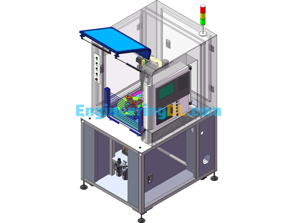
9.1 three-dimensional diagram of the equipment
9.2 two-dimensional diagram of the equipment
9.3 pneumatic system diagram
9.4 electrical schematic diagram
9.5 important outsourcing parts of the manual, certificate of conformity
Appendix 1: Electrical schematic diagram
Main circuit schematic diagram
Servo motor schematic diagram
Servo controller schematic diagram
PLC input schematic diagram
PLC input schematic diagram
PLC output schematic 1
PLC output schematic 2
PLC output schematic 3
Analog input circuit
Electric control cabinet
Original layout diagram
Specification: D077 Instrument Panel Punching Equipment 3D Exported
|
User Reviews
Be the first to review “D077 Instrument Panel Punching Equipment 3D Exported”
You must be logged in to post a review.

There are no reviews yet.