Square Electrical Box Injection Mold 3D+CAD Drawings (AutoCAD, UGNX), 3D Exported
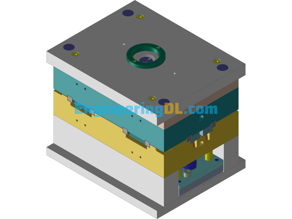
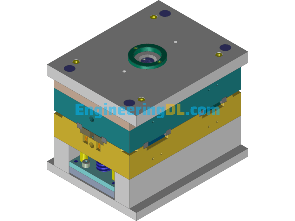
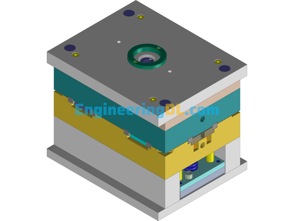
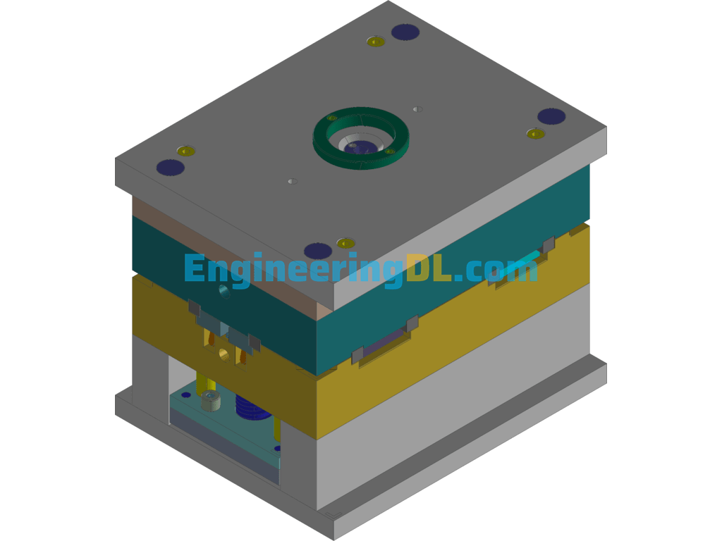

The mold is a three-dimensional two-dimensional design of an injection mold for an electrical square box. The mold frame adopts a three-plate mold frame, with a point sprue feed and a side core extraction mechanism.
The movement of this injection mold to open the mold and close the mold is briefly introduced as follows.
The action of opening the mold is introduced: when the injection molding machine completes the process of holding pressure and cooling molding, the next step is to open the injection mold, the power to open the injection mold is from the hydraulic cylinder at the back of the injection molding, when the injection control system issues the command to open the mold, the hydraulic cylinder starts to work, the cylinder drives the plate at the back of the injection molding to start the movement, because the moving part of the injection mold is fixed to the plate at the back of the injection molding As the moving part of the mold is fixed on the back of the plate, it will move to the back with the back of the plate, because the fixed part of the mold is fixed in front of the mold, it is stationary when the mold is opened, but this is a double parting surface mold frame structure, the cavity fixed plate is required to move.
Therefore, when the mold is opened
, the first parting is the first time, the cavity fixing plate is separated from the unloading plate, and the power to open the movement comes from the nylon plug mechanism installed between the fixed plate and the fixed plate of the moving mold, which completes the movement to the specified distance under the action of its friction, and this distance is the overall length of the manifold. As the slider is fixed on the fixed die plate and the tilt pin is fixed on the panel, the slider will move a distance relative to the tilt pin, and the tilt pin will produce the lateral core movement at the same time. Next is the second parting, on the basis of the completion of the first parting, continue to open the mold movement, this time the unloading plate will begin to move, the role of the unloading plate is to force the flow channel condensate and hook material rod separation, this movement distance is generally in 8mm ~ 10mm is sufficient, the same as the first mold opening, the slider and tilt pin is not Completely separated, continue the lateral core extraction and complete the core extraction action. The first two partings are used to open the mold space, so that the flow channel can have space to take out the condensed material.
3. Finally, the third parting, after the completion of the first two partings, continue to open the mold movement, it will separate the movable mold from the fixed mold at the parting surface. When the dynamic mold movement to the designated position of the injection molding machine, this time the product will have enough space to take out, at this time, the injection molding machine behind the configuration of the launch cylinder began to receive instructions to work, forward to launch action, from the launch cylinder comes with a round rod, the top of the injection mold push rod fixed plate to the front of the movement, the push rod fixed plate above the push rod directly to the inner surface of the plastic products, lowering the product out. The core of the mold is moved. After the product is pushed out, the product can be taken out and placed in the designated frame by the mechanical arm installed on the upper part of the injection molding machine, or the operator can take out the product and place it in the frame. This completes the opening action of the whole injection mold.
After the product is taken out, the injection molding will be closed. The power for closing the injection mold also comes from the hydraulic cylinder at the back of the injection molding, when the injection control system issues the mold closing command, the hydraulic cylinder starts to work, the cylinder drives the plate at the back of the injection molding to move forward, the dynamic mold part of the injection molding moves to the front together with the plate at the back of the injection molding, when the bevel of the slant pin contacts the bevel of the slider, the mold will be closed. When the bevel of the bevel pin touches the bevel of the slider, the slider will be reset, and when the reset lever of the moving mold touches the fixed plate of the fixed mold, the reset lever will drive the fixed plate of the pusher and the pusher to be reset.
Specification: Square Electrical Box Injection Mold 3D+CAD Drawings (AutoCAD, UGNX), 3D Exported
|
User Reviews
Be the first to review “Square Electrical Box Injection Mold 3D+CAD Drawings (AutoCAD, UGNX), 3D Exported”
You must be logged in to post a review.

There are no reviews yet.