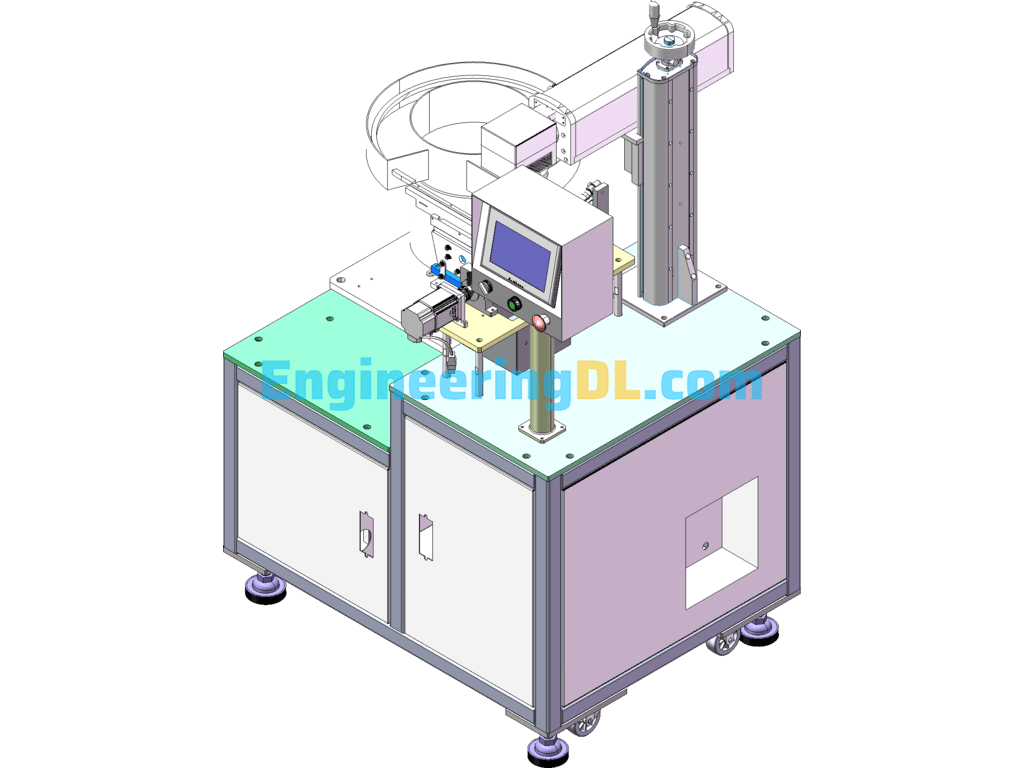
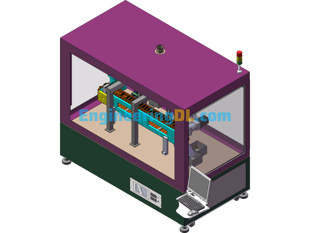
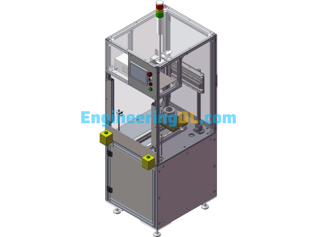
Rotary Laser Engraving Equipment Automatic Loading And Unloading Marking Machine (CreoProE), 3D Exported
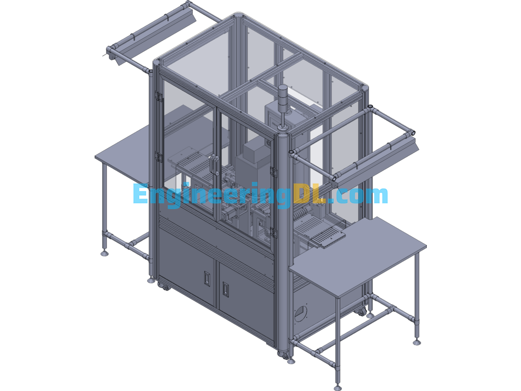
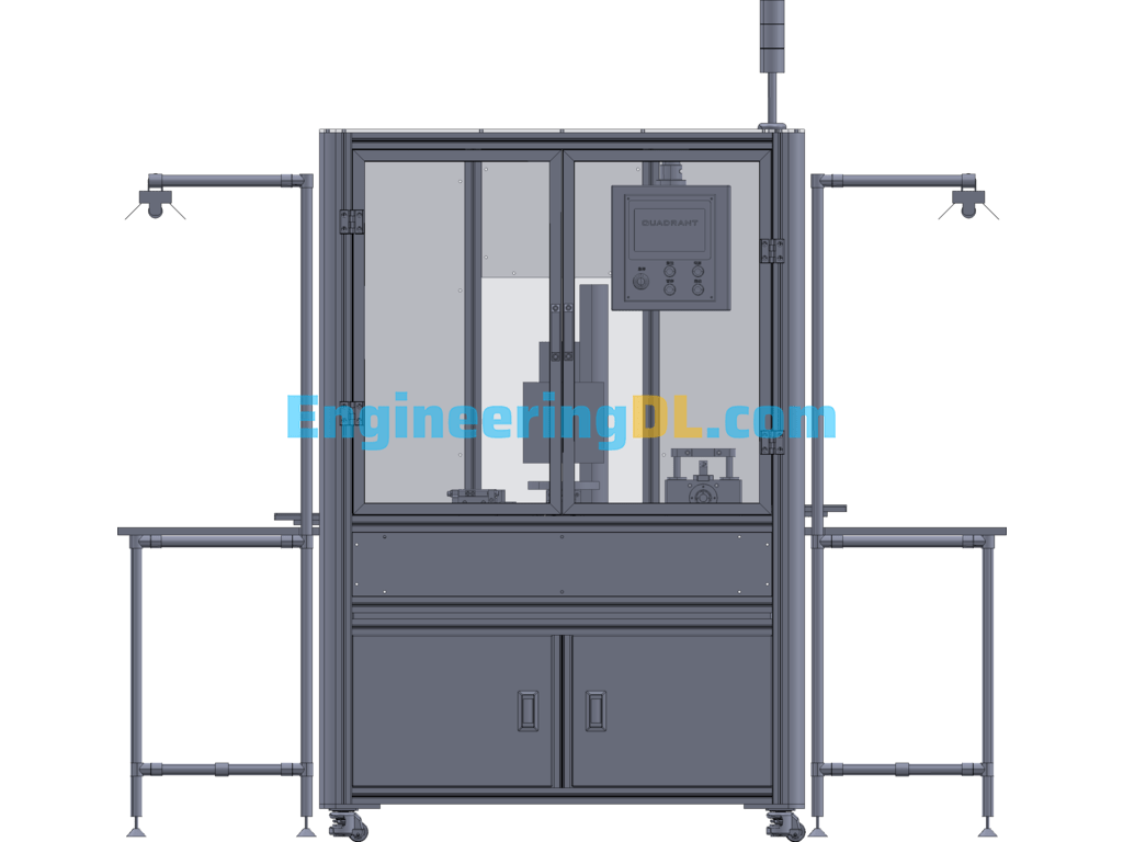
Laser engraving machine equipment function.
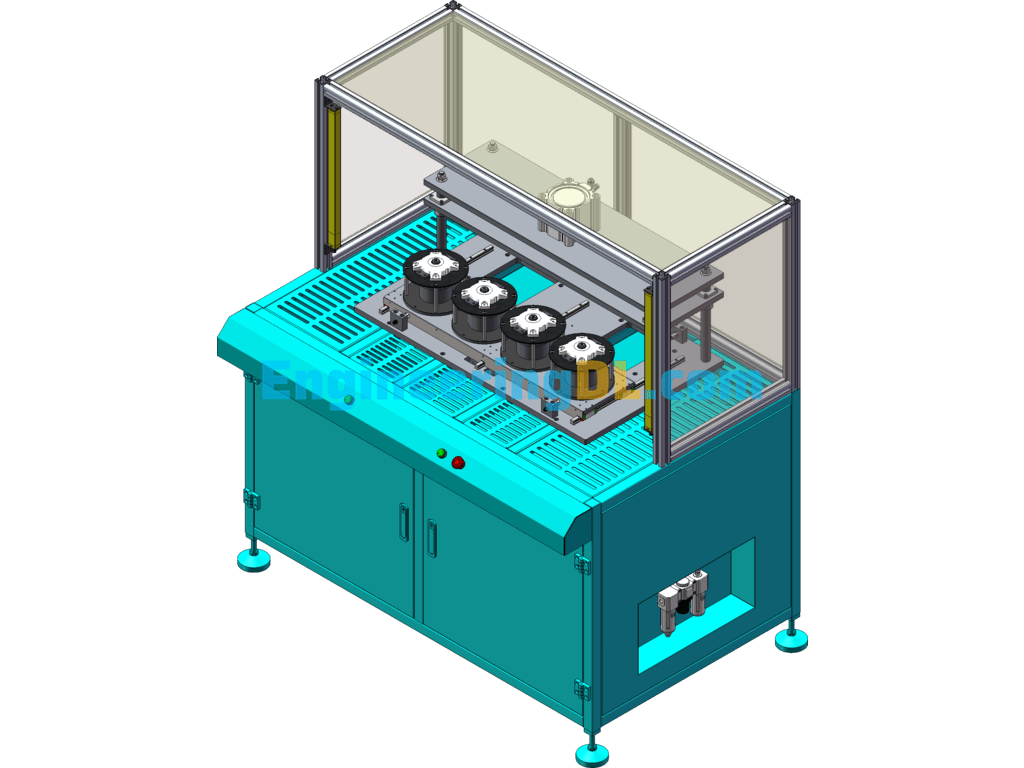
Loading and unloading by toggle type magnet loading and unloading mechanism, and adding rotating mechanism in the middle to complete product side marking operation and carrier transfer.
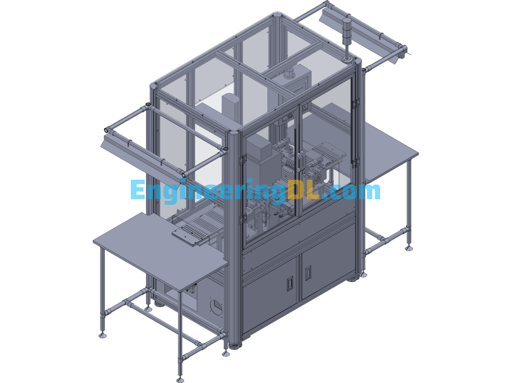
Equipment structure.
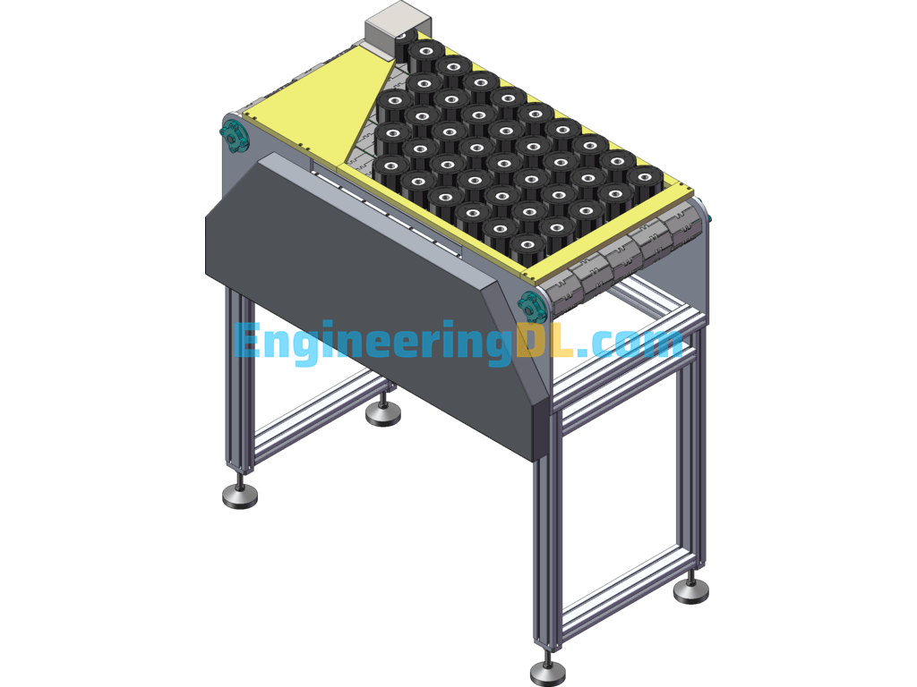
Magnet loading mechanism: Adopt the imitation shaped panning pushing piece to feed the material, the cylinder slide cover is staggered up and down, and the cylinder drives the pushing needle for loading action.
Laser engraving equipment: responsible for the marking function of the product.
Rotating mechanism: servo motor drives the fan-shaped roller, and the roller fan blade with magnet ensures that the workpiece does not fall off.
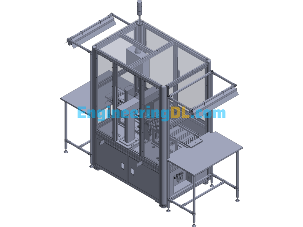
Magnet underfeeding mechanism: through two cylinders cooperate to realize the underfeeding function.
Translating feeding mechanism: through the imitation of the shape of the translating push piece, to ensure the stability of each feeding.
Feeding sliding mechanism: the misshift stall plate adopts epoxy plate + SUS430 combination material, which can ensure the magnet feeding in place and avoid the magnet up and down misshift magnet to prevent scratching.
Push magnet feeding mechanism: Adopt spring thimble to avoid magnet side scratches.
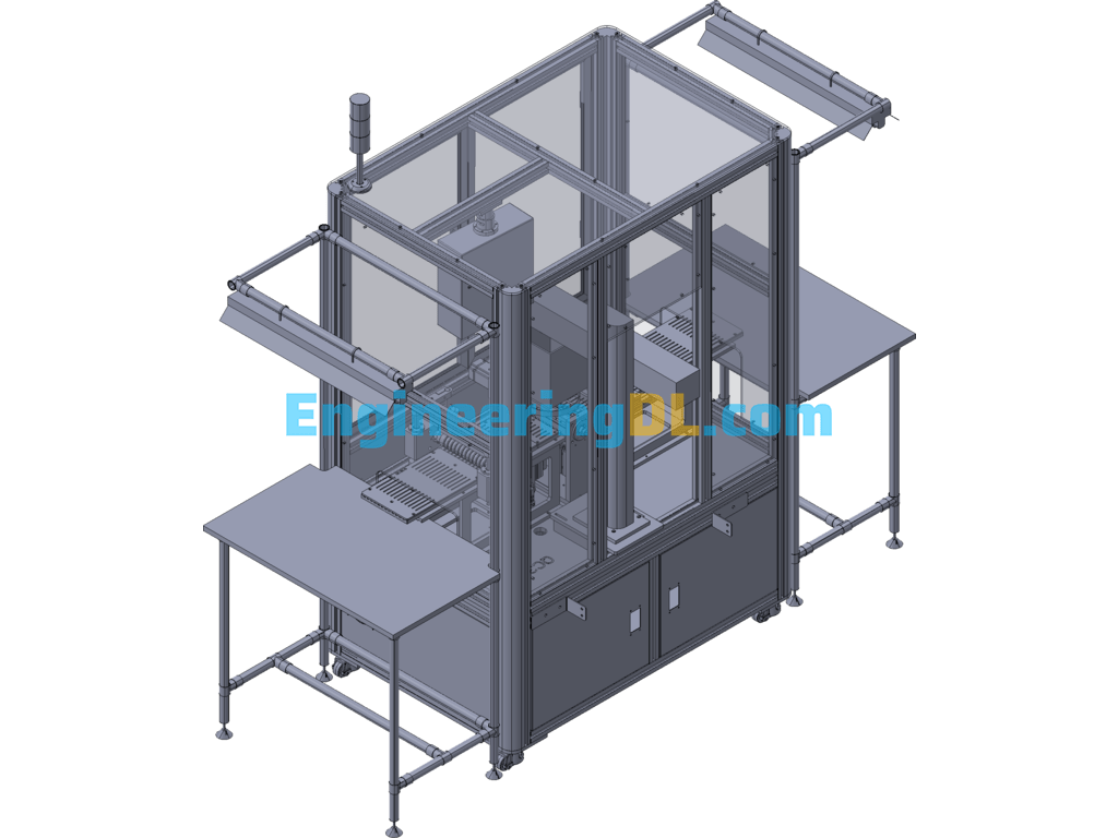
Down material plucking mechanism: two cylinders are used to drive the paddle to achieve the plucking function
Plucking mechanism: the paddle moves up to the carrier slot to pluck the product to the material channel.
Process flow.
Step 1: the cylinder of the magnet pulling mechanism tops the magnets tightly.
Step 2: the cylinder of the magnet pulling mechanism moves forward horizontally to advance the magnet.
Step 3: The wrongly divided bin moves upward to separate the magnets, and the end file sucks the magnets in.
Step 4: The cylinder of the magnet pulling mechanism moves down and retreats to the next pulling preparation.
Step 5: The pushing ejector pushes the magnets on the wrong parting plate into the fixture.
Step 6: The rotating mechanism rotates 90?? to set up the marking surface of the magnet to the marking machine for marking.
Step 7: the marking is finished and the rotating mechanism rotates the carrier to the lower material side.
Step 8: the cylinder of the magnet underfeed mechanism moves forward to the bottom of the carrier.
Step 9: the magnet downcomer mechanism moves up to insert inside the carrier.
Step 10: the cylinder of the magnet underfeeding mechanism moves back and pivots the product to the material plate to finish underfeeding.
Specification: Rotary Laser Engraving Equipment Automatic Loading And Unloading Marking Machine (CreoProE), 3D Exported
|
User Reviews
Be the first to review “Rotary Laser Engraving Equipment Automatic Loading And Unloading Marking Machine (CreoProE), 3D Exported”
You must be logged in to post a review.

There are no reviews yet.