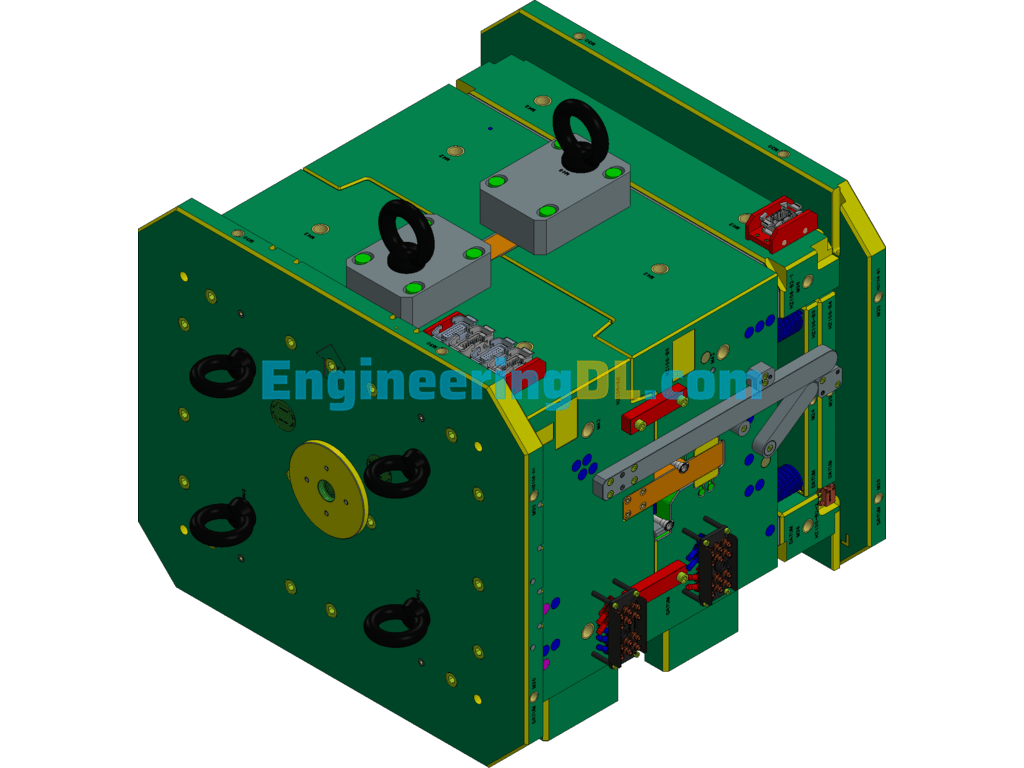
Intermediate Shaft Hydraulic Clamping Set-Up Diagram SolidWorks, 3D Exported
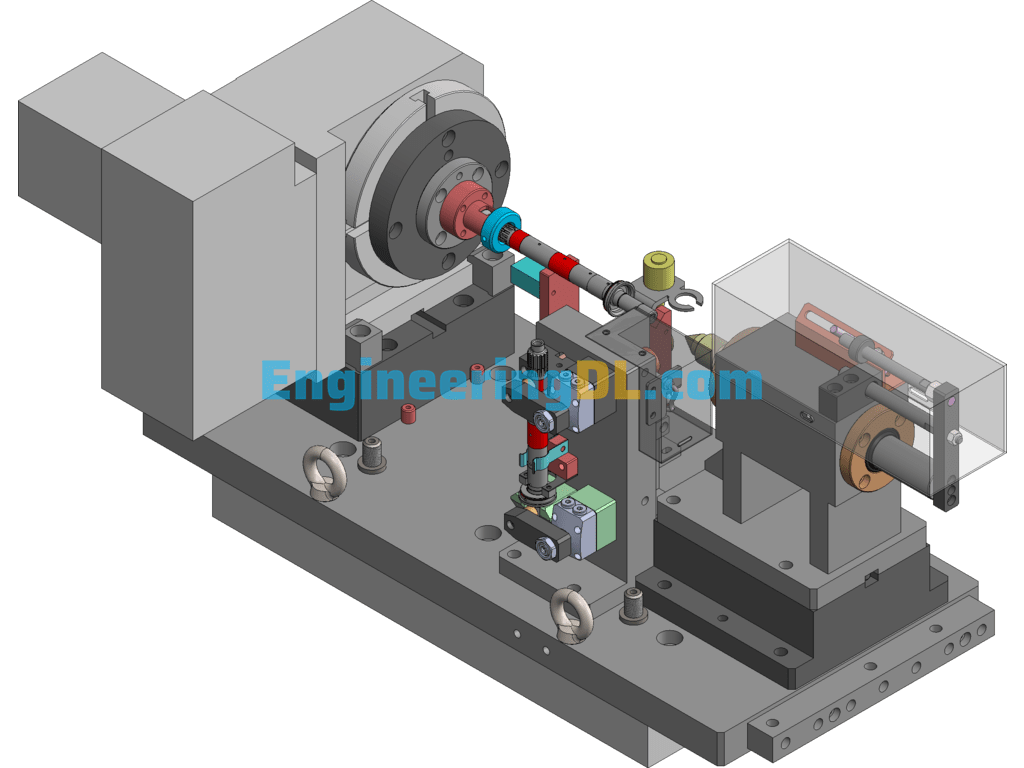
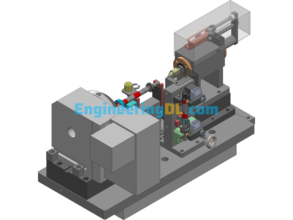
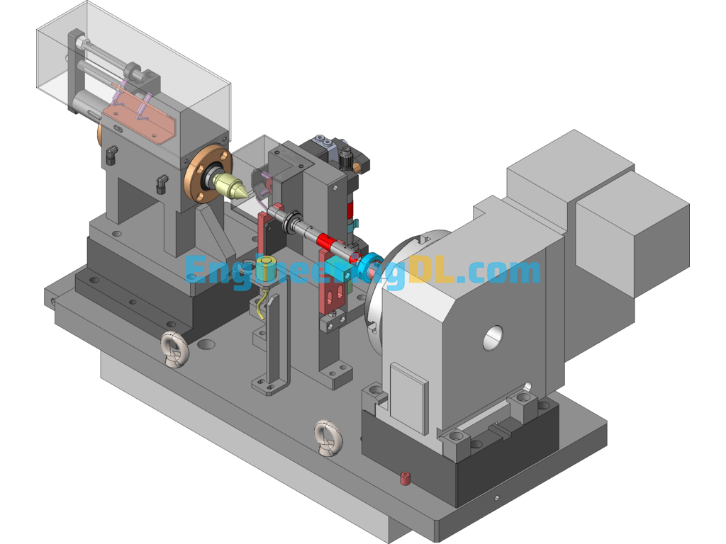
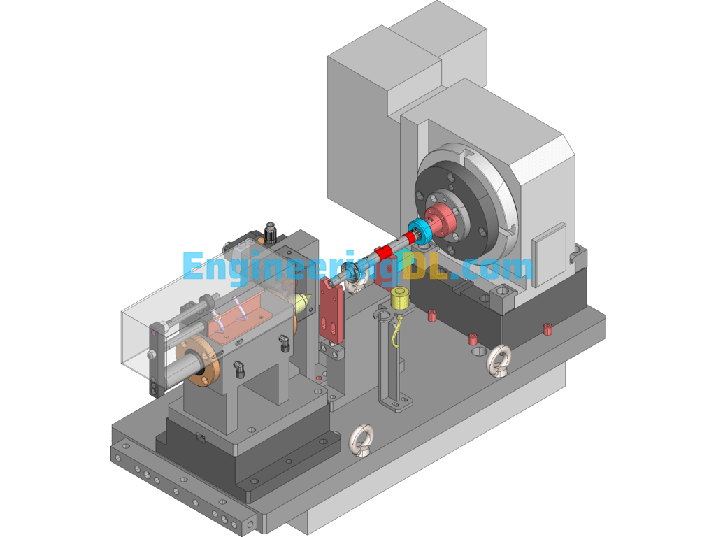
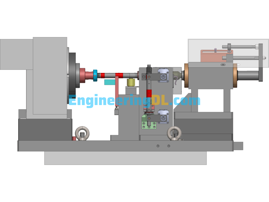
This diagram is the middle axis hydraulic fixture set-up diagram, with machine CMV-510A, table size 600X360; this fixture OP10 adopts workpiece center axis and spline end positioning; OP20 adopts V-block fixed workpiece center axis and bottom end positioning; OP10 oil circuit: 1 in 1 out; OP20 oil circuit: 1 in 1 out; turntable brake 1 way; fixture weight is about: 250KG;
Specification: Intermediate Shaft Hydraulic Clamping Set-Up Diagram SolidWorks, 3D Exported
|
User Reviews
Be the first to review “Intermediate Shaft Hydraulic Clamping Set-Up Diagram SolidWorks, 3D Exported”
You must be logged in to post a review.

Intermediate Shaft Hydraulic Clamping Set-Up Diagram SolidWorks, 3D Exported
There are no reviews yet.